
What this reference covers
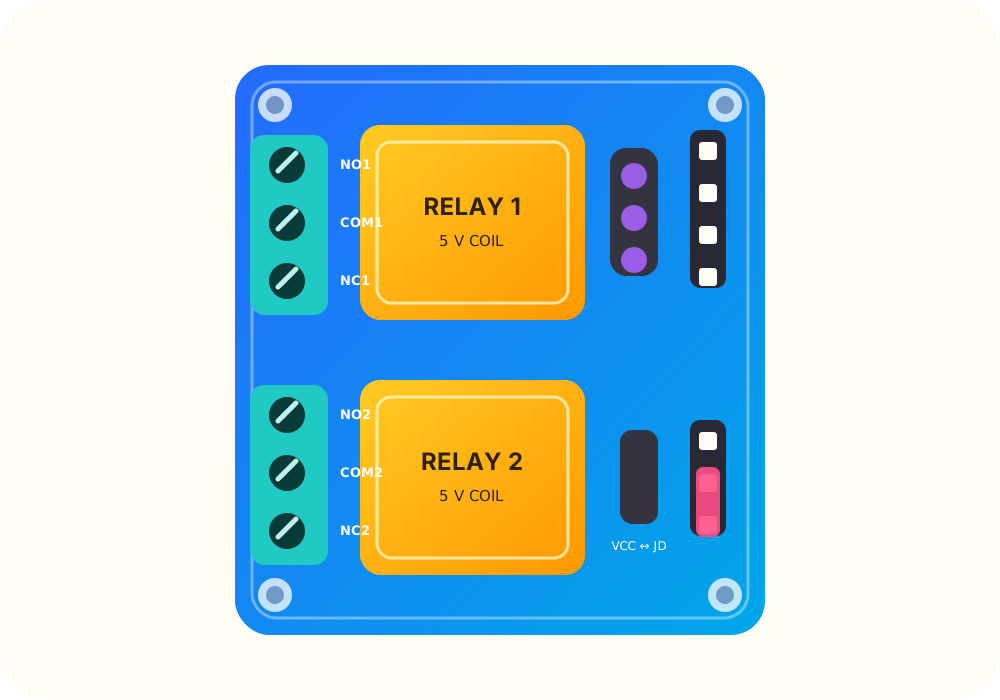
This draft models the current Kobee listing for the blue 5 V two-channel relay module shown in the product photography. The board has two three-position load terminal blocks, a four-pin control header and a three-pin relay-supply header with a removable VCC / JD-VCC jumper.
The exact PCB revision and relay manufacturer markings still need to be checked against physical Kobee stock before publication. Similar-looking relay boards can use different input circuits, active levels and jumper arrangements.
Low-voltage projects only
Kobee’s current product record deliberately limits this module to low-voltage loads. Do not use the exposed screw terminals for household mains. Electricity can cause shock, burns, fire or death; mains electrical work belongs with an appropriately licensed electrician and properly rated, enclosed equipment.
Relay contacts
Each channel is a single-pole, double-throw switch:
- COM is the moving common contact.
- NC is connected to COM while the relay is not energised.
- NO is connected to COM while the relay is energised.
The contact labels describe switching state only. They do not make a load safe or establish a usable current for every voltage, load type or enclosure.
Control and relay power
The control header exposes VCC, IN2, IN1 and GND. The separate JD-VCC header powers the relay side. With the factory jumper fitted, VCC and JD-VCC share the same 5 V supply. Removing the jumper can separate the controller-side and relay-side supplies, but only when the exact board revision and grounding arrangement have been verified.
Do not assume that a 3.3 V controller will reliably trigger IN1 or IN2. The input threshold and active polarity remain unverified for this generic revision.