
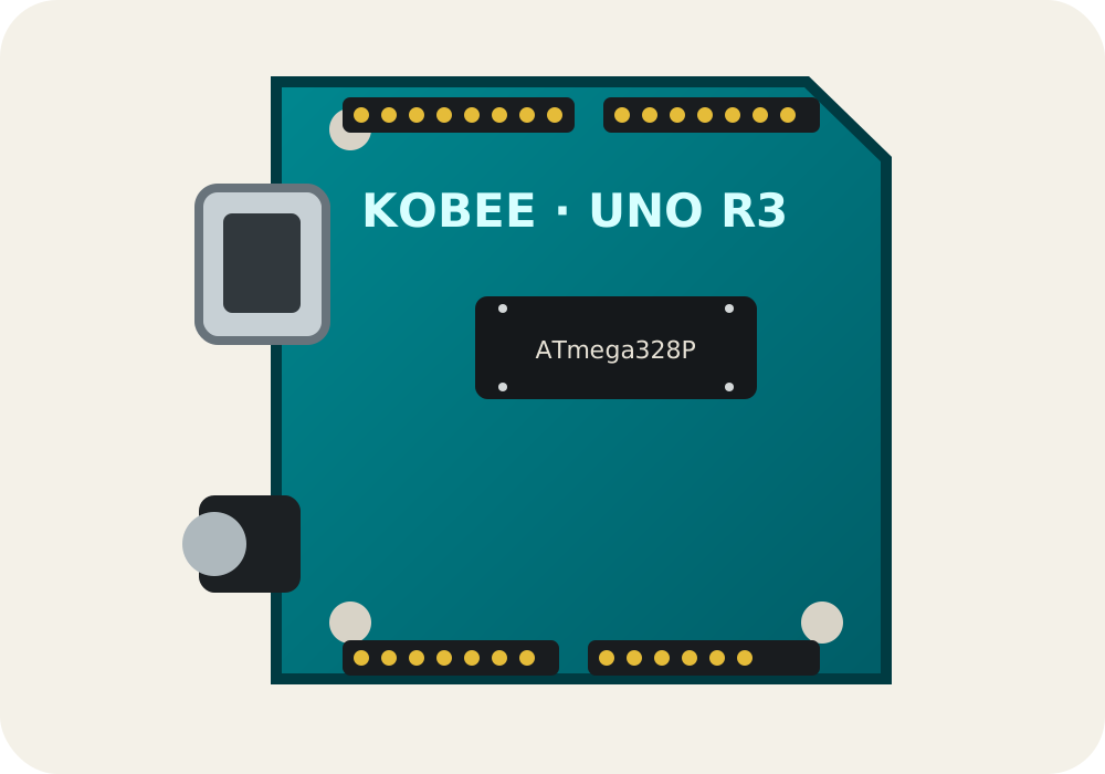
The classic Uno layout
This reference covers the Arduino Uno Rev3 with the socketed, dual-inline ATmega328P. Its familiar shield headers expose fourteen numbered digital pins and six analogue inputs, plus power, reset and reference connections.
Shared functions matter
Pins D0 and D1 form the hardware serial port used by the USB interface, so connected hardware can interfere with uploads and the Serial Monitor. D10–D13 carry SPI, while A4 and A5 carry I2C as SDA and SCL. The extra SDA and SCL header positions are duplicates of A4 and A5, not an additional bus.
PWM and analogue input
The ~ marking identifies the six pins supported by Arduino's analogWrite() convention: D3, D5, D6, D9, D10 and D11. A0–A5 are the primary analogue inputs and can also be addressed as digital GPIO when analogue conversion is not needed.
Power safely
The board's digital logic is 5 V. The VIN and USB limits are board power specifications, not GPIO signal limits. Always distinguish a recommended operating condition from an absolute maximum before connecting external circuits.