Learn / Pinouts / Espressif

ESP32-DevKitC V4 pinout

Explore every header pin on the ESP32-DevKitC V4 with ESP32-WROOM-32E, including GPIO suitability, boot cautions and default buses.

EspressifDevelopment boardESP32ESP32-WROOM-32E3.3 V logic2 × 19 pins26 usable GPIOWi-FiBluetooth
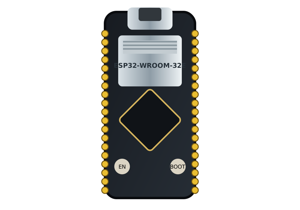
ESP32-DevKitC V4 board artworkKobee

Fast answers

Which GPIO should I use?

Start with what you are connecting. Click any GPIO to locate it in the interactive diagram and inspect the full reason.

Interactive shortlist
iiii!×××!!!!!!×××
Pin colour keyKobee
RecommendedUse with careAvoidSpecial case
Recommendation and GPIOs
Easy choice

Input-capable, no declared boot warning, and suitable for the ESP32 internal pull resistor.

Add an external resistor

Excellent inputs, including ADC1, but these input-only pins have no internal pull-up or pull-down.

Works with care

These pins are sampled during boot or share the programming serial connection. Your button circuit must not force the wrong reset-time level.

Do not use

Connected to the module flash. Treat these header positions as reserved.

Reference by function

See only the pins relevant to your circuit.

Each view removes the unrelated labels, then keeps the exact channel, bus role, and assignment status beside the physical board position.

01 · GPIO

GPIO pins: safe, conditional and avoid

Green pins are the easiest general-purpose choices. Amber pins have a device or board caveat. Red pins are reserved by the board or module.

VPinput onlyVNinput onlyIO34input onlyIO35input onlyIO32GPIO · remappableIO33GPIO · remappableIO25GPIO · remappableIO26GPIO · remappableIO27GPIO · remappableIO14GPIO · remappableIO12GPIO · remappableIO13GPIO · remappableD2GPIOD3GPIOCMDGPIOIO23GPIO · remappableIO22GPIO · remappableTXGPIO · remappableRXGPIO · remappableIO21GPIO · remappableIO19GPIO · remappableIO18GPIO · remappableIO5GPIO · remappableIO17GPIO · remappableIO16GPIO · remappableIO4GPIO · remappableIO0GPIO · remappableIO2GPIO · remappableIO15GPIO · remappableD1GPIOD0GPIOCLKGPIO
Pin colour keyKobee
GPIOADCDACTouchI2CSPIUARTPWM
02 · ADC

ADC analogue inputs

ADC1 is the practical choice while Wi-Fi is active. ADC2 remains useful when the radio is not using that hardware.

Input-only is not a disadvantage for a sensor input, but GPIO34–39 need an external pull resistor for a floating digital signal.

VPADC1_CH0VNADC1_CH3IO34ADC1_CH6IO35ADC1_CH7IO32ADC1_CH4IO33ADC1_CH5IO25ADC2_CH8IO26ADC2_CH9IO27ADC2_CH7IO14ADC2_CH6IO12ADC2_CH5IO13ADC2_CH4IO4ADC2_CH0IO0ADC2_CH1IO2ADC2_CH2IO15ADC2_CH3
Pin colour keyKobee
GPIOADCDACTouchI2CSPIUARTPWM
03 · DAC

DAC analogue outputs

These are the ESP32’s two true digital-to-analogue converter outputs. They are fixed channels, not PWM approximations.

IO25DAC1IO26DAC2
Pin colour keyKobee
GPIOADCDACTouchI2CSPIUARTPWM
04 · Touch

Capacitive touch inputs

Each highlighted pin has a fixed touch channel. The same physical pin may still serve other GPIO or analogue functions.

IO32TOUCH9IO33TOUCH8IO27TOUCH7IO14TOUCH6IO12TOUCH5IO13TOUCH4IO4TOUCH0IO0TOUCH1IO2TOUCH2IO15TOUCH3
Pin colour keyKobee
GPIOADCDACTouchI2CSPIUARTPWM
05 · I2C

I²C data and clock

GPIO21 and GPIO22 are the familiar defaults. The GPIO matrix can route I²C elsewhere, so default does not mean permanently fixed.

IO22I2C0 · SCL · defaultIO21I2C0 · SDA · default
Pin colour keyKobee
GPIOADCDACTouchI2CSPIUARTPWM
06 · SPI

SPI buses

VSPI and HSPI defaults are shown with their signal roles. Flash connections are deliberately excluded from the usable bus view.

A remappable peripheral still has electrical and boot restrictions. Remapping does not make a reserved pin safe.

IO14HSPI · SCK · defaultIO12HSPI · MISO · defaultIO13HSPI · MOSI · defaultIO23VSPI · MOSI · defaultIO19VSPI · MISO · defaultIO18VSPI · SCK · defaultIO5VSPI · CS · defaultIO15HSPI · CS · default
Pin colour keyKobee
GPIOADCDACTouchI2CSPIUARTPWM
07 · UART

UART serial ports

UART2 is the practical peripheral pair on this WROOM board. UART0 is connected to the USB programming bridge and is best kept free for upload and logs.

TXUART0 · TX · defaultRXUART0 · RX · defaultIO17UART2 · TX · defaultIO16UART2 · RX · default
Pin colour keyKobee
GPIOADCDACTouchI2CSPIUARTPWM
08 · PWM

PWM outputs

PWM can be routed to output-capable GPIOs. Input-only pins are not included because they cannot drive a PWM waveform.

IO32PWM · remappableIO33PWM · remappableIO25PWM · remappableIO26PWM · remappableIO27PWM · remappableIO14PWM · remappableIO12PWM · remappableIO13PWM · remappableIO23PWM · remappableIO22PWM · remappableTXPWM · remappableRXPWM · remappableIO21PWM · remappableIO19PWM · remappableIO18PWM · remappableIO5PWM · remappableIO17PWM · remappableIO16PWM · remappableIO4PWM · remappableIO0PWM · remappableIO2PWM · remappableIO15PWM · remappable
Pin colour keyKobee
GPIOADCDACTouchI2CSPIUARTPWM

The exact board this reference covers

This reference is for the 38-pin ESP32-DevKitC V4 fitted with an ESP32-WROOM-32E. Match both markings before wiring because other DevKitC and WROVER variants expose different connections.

Three rules that prevent most pin problems

Start with a green recommended pin. Prefer ADC1 for analogue readings while Wi-Fi is running. Keep GPIO6–11 free because the WROOM module uses them for flash.

Boot and button caveats

GPIO0, GPIO2, GPIO5, GPIO12 and GPIO15 are sampled during reset, so an attached circuit must not force the wrong boot level. GPIO34, GPIO35, GPIO36 and GPIO39 are input-only and have no internal pull resistor; use an external resistor for a button or other floating signal.

Programming and power

GPIO1 and GPIO3 connect to the USB-to-UART bridge. Attached hardware can disrupt firmware uploads or serial logs. The board uses 3.3 V logic; never apply a 5 V logic signal directly to a GPIO, and power the board from only one supply path at a time.

Fast troubleshooting

If the board will not boot, disconnect circuits from the strapping pins. If uploads fail, remove hardware from GPIO1 and GPIO3. If an analogue reading stops when Wi-Fi starts, move it to ADC1. If a button on GPIO34–39 floats, add an external pull resistor.

Quick explanations

ESP32 pinout FAQ

Which ESP32 GPIO pins are the easiest to use?

Start with the pins marked recommended: GPIO32, GPIO33, GPIO25, GPIO26, GPIO27, GPIO14, GPIO13, GPIO23, GPIO22, GPIO21, GPIO19, GPIO18, GPIO17, GPIO16, GPIO4. They are declared as general-purpose GPIO without a board-specific boot, programming, or reserved-function warning in this reference. Always check the exact function you need before wiring.

Which pins should I avoid on the ESP32-DevKitC V4?

Avoid GPIO9, GPIO10, GPIO11, GPIO8, GPIO7, GPIO6 for ordinary project wiring. Each is marked avoid for this exact hardware; open the pin in the interactive diagram to see its revision-specific warning and source.

Which pins can I use for a push button?

Use a recommended, input-capable GPIO. GPIO36, GPIO39, GPIO34, GPIO35 can also read a button but have no internal pull-up or pull-down, so they need an external resistor.

Which ESP32 pins are input-only?

GPIO36, GPIO39, GPIO34, GPIO35 are input-only on this device. They can read digital or analogue signals where supported, but they cannot drive an LED, PWM output, or other load.

Which analogue pins should I use while Wi-Fi is active?

Prefer the ADC1 pins: GPIO36, GPIO39, GPIO34, GPIO35, GPIO32, GPIO33. On this processor, ADC2 has a wireless-use conflict recorded in the pin definition, so ADC1 is the dependable starting point when radio operation and analogue sampling must coexist.

What are the default I2C pins?

The default I2C pins are GPIO22 (SCL) and GPIO21 (SDA).

Which pins provide true DAC output?

GPIO25 (DAC1) and GPIO26 (DAC2) provide the fixed DAC channels. A DAC produces an analogue output; it is different from PWM and from an ADC input.

Can I connect 5 V logic directly to the ESP32-DevKitC V4?

3.3 V GPIO only: ESP32 GPIO uses 3.3 V logic and is not 5 V tolerant. Add appropriate level shifting before connecting a 5 V signal. Power-input voltage and GPIO signal tolerance are separate specifications.

Searchable without JavaScript

Complete pin table

Every physical connection and declared alternate function is included here for accessibility, printing and search discovery.

PhysicalPinInput / outputGeneral suitabilityFunctionsImportant notes
J2.13V3Input + Outputunavailable
  • Power · 3.3 V rail · fixed
    J2.2ENCHIP_PUInputunavailable
    • Reset · enable/reset input · fixed
      J2.3VPGPIO36, SENSOR_VPInputconditional
      • GPIO · input only · fixed
      • ADC · ADC1_CH0 · 0 · fixed
      • Interrupt · remappable
      • No internal pull-up or pull-down circuitry; add an external resistor for a button
      • Input only; this pin cannot drive an output.
      J2.4VNGPIO39, SENSOR_VNInputconditional
      • GPIO · input only · fixed
      • ADC · ADC1_CH3 · 3 · fixed
      • Interrupt · remappable
      • No internal pull-up or pull-down circuitry; add an external resistor for a button
      • Input only; this pin cannot drive an output.
      J2.5IO34GPIO34Inputconditional
      • GPIO · input only · fixed
      • ADC · ADC1_CH6 · 6 · fixed
      • Interrupt · remappable
      • No internal pull-up or pull-down circuitry; add an external resistor for a button
      • Input only; this pin cannot drive an output.
      J2.6IO35GPIO35Inputconditional
      • GPIO · input only · fixed
      • ADC · ADC1_CH7 · 7 · fixed
      • Interrupt · remappable
      • No internal pull-up or pull-down circuitry; add an external resistor for a button
      • Input only; this pin cannot drive an output.
      J2.7IO32GPIO32Input + Outputrecommended
      • GPIO · remappable
      • ADC · ADC1_CH4 · 4 · fixed
      • Touch · TOUCH9 · 9 · fixed
      • PWM · remappable
      • Interrupt · remappable
      • I2S · remappable
        J2.8IO33GPIO33Input + Outputrecommended
        • GPIO · remappable
        • ADC · ADC1_CH5 · 5 · fixed
        • Touch · TOUCH8 · 8 · fixed
        • PWM · remappable
        • Interrupt · remappable
        • I2S · remappable
          J2.9IO25GPIO25Input + Outputrecommended
          • GPIO · remappable
          • ADC · ADC2_CH8 · 8 · fixed
          • DAC · DAC1 · 1 · fixed
          • PWM · remappable
          • Interrupt · remappable
          • I2S · remappable
            J2.10IO26GPIO26Input + Outputrecommended
            • GPIO · remappable
            • ADC · ADC2_CH9 · 9 · fixed
            • DAC · DAC2 · 2 · fixed
            • PWM · remappable
            • Interrupt · remappable
            • I2S · remappable
              J2.11IO27GPIO27Input + Outputrecommended
              • GPIO · remappable
              • ADC · ADC2_CH7 · 7 · fixed
              • Touch · TOUCH7 · 7 · fixed
              • PWM · remappable
              • Interrupt · remappable
              • I2S · remappable
                J2.12IO14GPIO14, MTMSInput + Outputrecommended
                • GPIO · remappable
                • ADC · ADC2_CH6 · 6 · fixed
                • Touch · TOUCH6 · 6 · fixed
                • PWM · remappable
                • Interrupt · remappable
                • SPI · SCK · default
                  J2.13IO12GPIO12, MTDIInput + Outputconditional
                  • GPIO · remappable
                  • ADC · ADC2_CH5 · 5 · fixed
                  • Touch · TOUCH5 · 5 · fixed
                  • PWM · remappable
                  • Interrupt · remappable
                  • SPI · MISO · default
                  • Strapping pin sampled during reset
                  • A wrong reset-time level can select an incompatible flash voltage.
                  J2.14GNDunavailable
                  • Ground · fixed
                    J2.15IO13GPIO13, MTCKInput + Outputrecommended
                    • GPIO · remappable
                    • ADC · ADC2_CH4 · 4 · fixed
                    • Touch · TOUCH4 · 4 · fixed
                    • PWM · remappable
                    • Interrupt · remappable
                    • SPI · MOSI · default
                      J2.16D2GPIO9Input + Outputavoid
                      • GPIO · fixed
                      • SPI · flash data 2 · fixed
                      • Connected internally to SPI flash; using it can stop code execution.
                      J2.17D3GPIO10Input + Outputavoid
                      • GPIO · fixed
                      • SPI · flash data 3 · fixed
                      • Connected internally to SPI flash; using it can stop code execution.
                      J2.18CMDGPIO11Input + Outputavoid
                      • GPIO · fixed
                      • SPI · flash command · fixed
                      • Connected internally to SPI flash; using it can stop code execution.
                      J2.195VInput + Outputunavailable
                      • Power · 5 V rail · fixed
                      • Use only one board power source at a time.
                      J3.1GNDunavailable
                      • Ground · fixed
                        J3.2IO23GPIO23Input + Outputrecommended
                        • GPIO · remappable
                        • PWM · remappable
                        • Interrupt · remappable
                        • SPI · MOSI · default
                        • I2S · remappable
                          J3.3IO22GPIO22Input + Outputrecommended
                          • GPIO · remappable
                          • PWM · remappable
                          • Interrupt · remappable
                          • I2C · SCL · default
                          • I2S · remappable
                            J3.4TXGPIO1, U0TXDInput + Outputconditional
                            • GPIO · remappable
                            • UART · TX · default
                            • PWM · remappable
                            • Interrupt · remappable
                            • Connected to the on-board USB-to-UART bridge
                            • Activity here can interfere with flashing and serial logs.
                            J3.5RXGPIO3, U0RXDInput + Outputconditional
                            • GPIO · remappable
                            • UART · RX · default
                            • PWM · remappable
                            • Interrupt · remappable
                            • Connected to the on-board USB-to-UART bridge
                            • External drive can interfere with flashing and serial communication.
                            J3.6IO21GPIO21Input + Outputrecommended
                            • GPIO · remappable
                            • PWM · remappable
                            • Interrupt · remappable
                            • I2C · SDA · default
                            • I2S · remappable
                              J3.7GNDunavailable
                              • Ground · fixed
                                J3.8IO19GPIO19Input + Outputrecommended
                                • GPIO · remappable
                                • PWM · remappable
                                • Interrupt · remappable
                                • SPI · MISO · default
                                • I2S · remappable
                                  J3.9IO18GPIO18Input + Outputrecommended
                                  • GPIO · remappable
                                  • PWM · remappable
                                  • Interrupt · remappable
                                  • SPI · SCK · default
                                  • I2S · remappable
                                    J3.10IO5GPIO5Input + Outputconditional
                                    • GPIO · remappable
                                    • PWM · remappable
                                    • Interrupt · remappable
                                    • SPI · CS · default
                                    • Strapping pin sampled during reset
                                    • Do not force an incompatible level while the chip resets.
                                    J3.11IO17GPIO17Input + Outputrecommended
                                    • GPIO · remappable
                                    • UART · TX · default
                                    • PWM · remappable
                                    • Interrupt · remappable
                                    • Available on ESP32-WROOM modules; not available with ESP32-WROVER modules
                                    J3.12IO16GPIO16Input + Outputrecommended
                                    • GPIO · remappable
                                    • UART · RX · default
                                    • PWM · remappable
                                    • Interrupt · remappable
                                    • Available on ESP32-WROOM modules; not available with ESP32-WROVER modules
                                    J3.13IO4GPIO4Input + Outputrecommended
                                    • GPIO · remappable
                                    • ADC · ADC2_CH0 · 0 · fixed
                                    • Touch · TOUCH0 · 0 · fixed
                                    • PWM · remappable
                                    • Interrupt · remappable
                                      J3.14IO0GPIO0, BOOTInput + Outputconditional
                                      • GPIO · remappable
                                      • ADC · ADC2_CH1 · 1 · fixed
                                      • Touch · TOUCH1 · 1 · fixed
                                      • PWM · remappable
                                      • Interrupt · remappable
                                      • Boot strapping pin; low during reset enters download mode
                                      • Holding this pin low during reset enters firmware download mode.
                                      J3.15IO2GPIO2Input + Outputconditional
                                      • GPIO · remappable
                                      • ADC · ADC2_CH2 · 2 · fixed
                                      • Touch · TOUCH2 · 2 · fixed
                                      • PWM · remappable
                                      • Interrupt · remappable
                                      • Strapping pin sampled during reset
                                      • External circuitry must allow the correct reset-time level.
                                      J3.16IO15GPIO15, MTDOInput + Outputconditional
                                      • GPIO · remappable
                                      • ADC · ADC2_CH3 · 3 · fixed
                                      • Touch · TOUCH3 · 3 · fixed
                                      • PWM · remappable
                                      • Interrupt · remappable
                                      • SPI · CS · default
                                      • Strapping pin sampled during reset
                                      • External circuitry must allow the correct reset-time level.
                                      J3.17D1GPIO8Input + Outputavoid
                                      • GPIO · fixed
                                      • SPI · flash data 1 · fixed
                                      • Connected internally to SPI flash; using it can stop code execution.
                                      J3.18D0GPIO7Input + Outputavoid
                                      • GPIO · fixed
                                      • SPI · flash data 0 · fixed
                                      • Connected internally to SPI flash; using it can stop code execution.
                                      J3.19CLKGPIO6Input + Outputavoid
                                      • GPIO · fixed
                                      • SPI · flash clock · fixed
                                      • Clock · flash clock · fixed
                                      • Connected internally to SPI flash; using it can stop code execution.