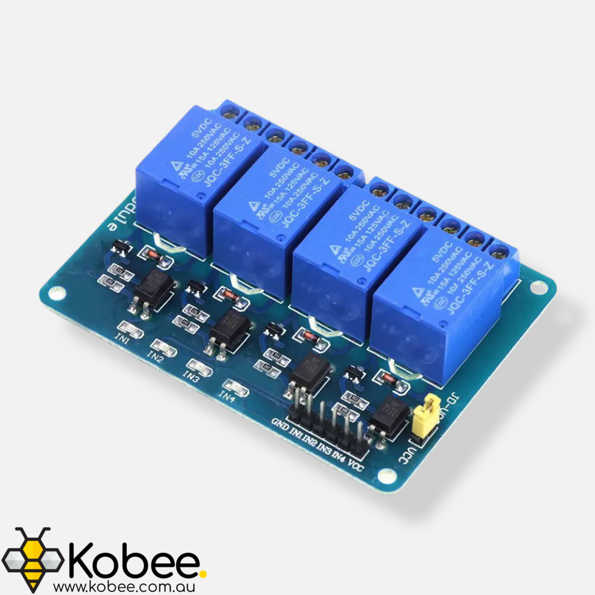
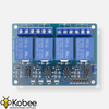
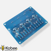
12V Quad Channel Relay Module 10A
Warning This board is not designed to be utilised with mains voltages and is intended for low voltage applications only.

12V Quad Channel Relay Module 10A
Available:
Out of Stock
- Product SKU: NA191
- Category: Arduino Accessories, Best Sellers, Components, New Products, Relays
$5.99
These versatile 12V relay modules allow you to control 4 larger devices up to 10A using whatever flavour of microcontroller you prefer or even a simple button and come with optoisolation
- Compatible with all microcontroller boards including Arduino and ESP variants
- The relay is designed to operate up to 30VAC or 30VDC at 10A
- Capable of controlling 4 devices (Quad Channel)
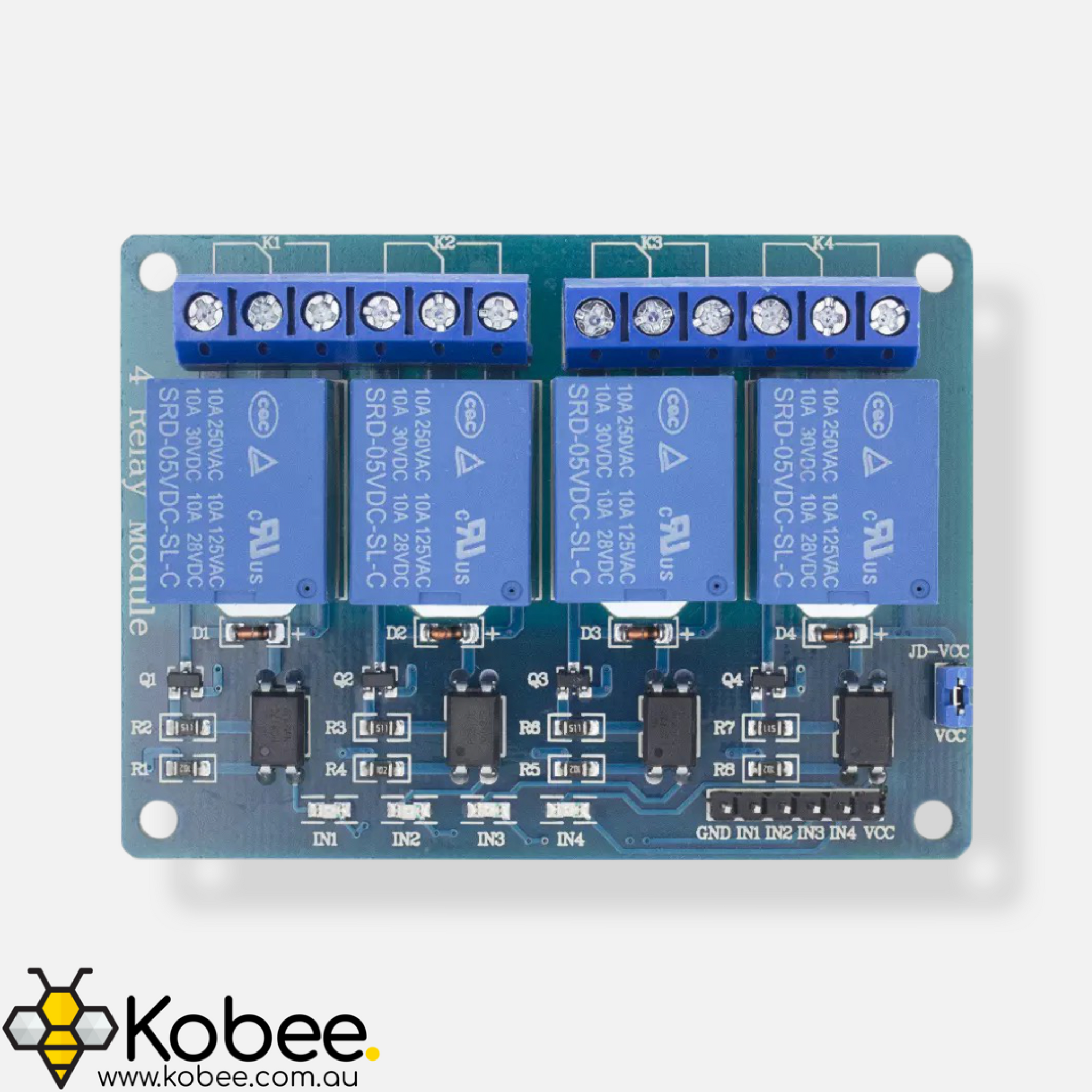
- The module has onboard optoisolators which seperate the input and output sides of the circuit. If you would like to take advantage of the optoisolation you must use a seperate 5V supply to power the relay coil and the input circuitry. See the Pinout Guide tab for more information
- 4 onboard LEDs show you the state of the relay
- The relay is activated when the input pin is pulled low to ground. If the input pin is floating or at VCC, the relay will inactivate
Refer to Pinout tab for an explanation of the relavent pins on the module
Warning This board is not designed to be utilised with mains voltages and is intended for low voltage applications only.
Working with high voltage electricity can result in personal injury and / or property damage

| Label | Name | Notes |
|---|---|---|
| NO | Normally Open | Pin is normally disconnected fromcommon unless relay is activated |
| COM | Common | Connected to circuit you are planning to switch |
| NC | Normally Closed | Pin is normally connected to common unless relay is activated |
| VCC | Voltage input | Input Voltage for control circuit and relay coil - 12V |
| JD-VCC | Alternate Voltage input | If optoisolation is required, remove the jumper and apply a seperate voltage source between VCC and GND If optoisolation is not required, connect the jumper between VCC and JD-VCC. The relay coil will be powered by the same voltage source as the input circuitry / microcontroller |
| GND | Ground | Common Ground Connection |
| IN | Input | Pin used to control the relay (Connected to output of microcontroller or switch. Pin is active low meaning it will be activated when you pull the pin low |


